Stimulation
The Stimulation module, located in the System tab, is used to configure the parameters for intracortical microstimulation. This approach involves the invasive activation of neurons and is being investigated as a means to deliver sensory percepts in cases where sensory pathways have been damaged.
Within the Stimulation module, you can define the specific parameters for the stimulation, including the amplitude, duration, and frequency of the electrical pulses. These parameters can be adjusted based on the experimental requirements and the targeted neural population.
By configuring the stimulation parameters in the Stimulation module, researchers can precisely control and deliver electrical stimulation to specific brain regions, allowing for the exploration of sensory perception and the potential restoration of sensory function in cases of sensory pathway damage.
It's worth noting that the Stimulation module is just one component of Allego's comprehensive system, designed to provide researchers with a wide range of tools and features for experimental control and data analysis in the field of neuroscience.
To configure the stimulation parameters for a specific headstage channel in Allego, follow these steps:
-
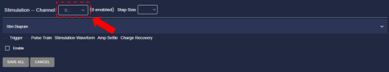
Click on the desired channel in the Allego interface to select it.
-
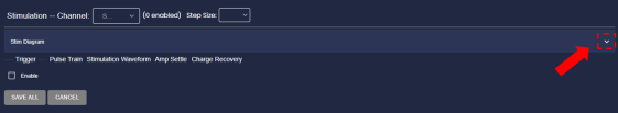
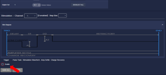
Locate the expander arrow on the right side of the Stim Diagram panel to expand the display.
-
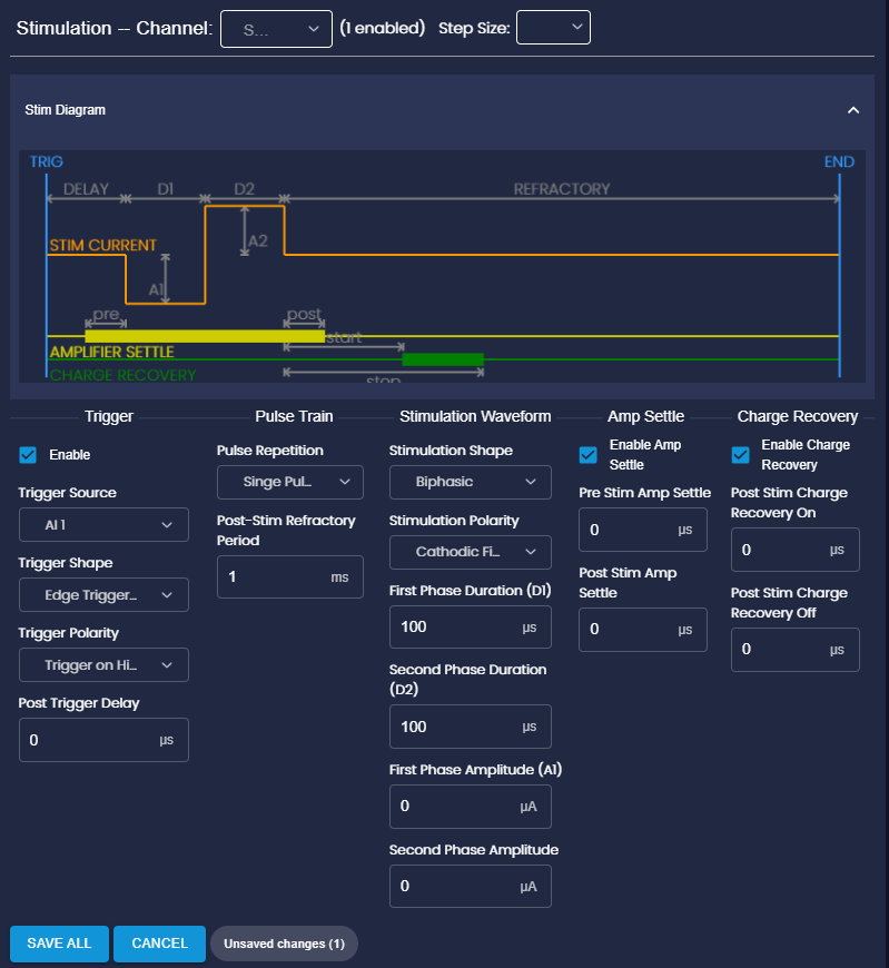
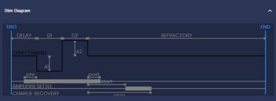
This display is an illustration of the stimulation waveform (please note that the illustration is not to scale). This visualization can help you understand and visualize the stimulation waveform.
-
Underneath the expanded display window, you will find the stimulation trigger settings. Enable the stimulation trigger by checking the "Enable" box.
-
Once the stimulation trigger is enabled, a Stimulation Parameters window will appear. This window allows you to adjust the stimulation parameters for the selected channel.This visualization can help you understand and visualize the stimulation waveform.

-
Within the Stimulation Parameters window, you can modify the parameters such as the amplitude and duration of the stimulation pulse, and the frequency of the stimulation waveform. Adjust these parameters according to your experimental requirements.
-
When you select or interact with the stimulation parameter controls, you will notice that the corresponding arrows and labels in the waveform display(Stim Diagram) turn from light gray to red. This visual indication is provided to assist you in identifying and adjusting the specific parameters being modified.
-
After configuring the stimulation parameters to your desired settings, click on the "SAVE ALL" button to apply the changes.
By following these steps and adjusting the stimulation parameters for specific headstage channels, you can precisely control the electrical stimulation delivered to the target tissue. This level of control is valuable for various experimental and therapeutic applications that involve intracortical microstimulation.
Note: The exact user interface and layout may vary slightly depending on the system mode you are using, but the general steps for configuring stimulation parameters should remain similar.
Stimulation Trigger
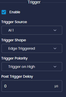
To adjust the stimulation parameters in Allego, you can select a trigger source from various options:
Trigger Source:
-
Digital or Analog Inputs: Choose any available digital or analog input on the main Controller or optional I/O Expander as the trigger source. Analog inputs can function as digital inputs with a threshold of 1.65 V.
-
Host Computer's Number Keys: You can use the number keys (1-8) on your computer's keyboard as triggers for the stimulation.
Trigger Shape:
Once you have selected the trigger source, you can configure the stimulation sequence type:
-
Edge Triggered: Selecting this option will cause the stimulation sequence to execute once every time the trigger changes from an inactive state to an active state.
-
Level Triggered: Selecting this option will cause the stimulation sequence to execute repeatedly as long as the trigger source remains in an active state.
Trigger Polarity:
You can also specify the active level for the trigger source:
-
Active on High: Choose this option if the trigger source is considered active when it has a "high" logic level or when a key is pressed.
-
Active on Low: Choose this option if the trigger source is considered active when it has a "low" logic level or when a key is not pressed.
Post Trigger Delay:
Additionally, you have the option to introduce a post-trigger delay:
By default, the stimulation sequence executes immediately after a trigger event. However, you can specify a post-trigger delay of up to 500 milliseconds. This feature allows you to stagger stimulation pulses across multiple channels triggered by the same source.
These settings provide flexibility in configuring the stimulation parameters based on your experimental needs. You can define the trigger source, sequence type, active level, and introduce delays to precisely control the stimulation events in Allego.
Pulse Train
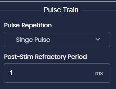
Pulse Repetition: Within Allego's stimulation module, you have the flexibility to configure both single pulses and pulse trains as stimulation sequences. The pulse repetition selector allows you to choose between these options based on your experimental requirements.
If you select a pulse train, you can define the number of pulses in the train (up to 256) and the pulse train period (up to 1 second). The corresponding frequency of the pulse train will be displayed below for your reference.
Post-Stim Refractory Period: Additionally, you have the option to set a post-stimulation refractory period. During this period, any additional trigger events will be ignored after a stimulation sequence has completed. This parameter is useful for configuring pulse trains of indefinite duration by combining single stimulation pulses with level triggering. As long as the trigger source remains high, the single stimulation pulse will repeat at a rate determined by the post-stimulation refractory period, which can be set up to one second.
Stimulation Waveform
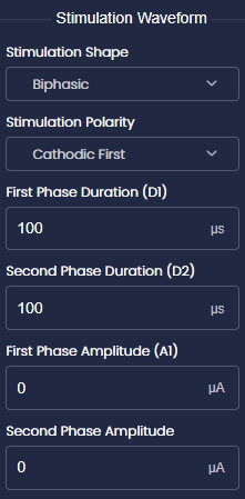
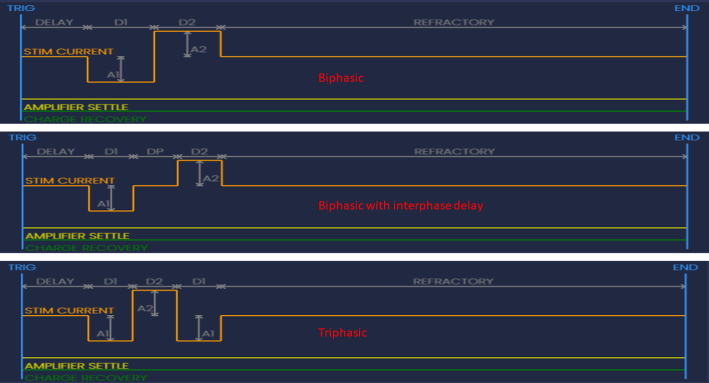
Stimulation Shape: Allego's stimulation system offers support for three waveform shapes: biphasic, biphasic with interphase delay, and triphasic. These waveform options provide flexibility in designing the stimulation patterns for your specific experimental requirements.
-
The biphasic waveform consists of two phases, typically a positive pulse followed by a negative pulse. This waveform shape is commonly used in various stimulation applications.
-
The biphasic waveform with interphase delay includes an additional delay period between the positive and negative phases. This delay can be adjusted to achieve specific timing requirements in your stimulation protocol.
-
The triphasic waveform extends the biphasic waveform by adding a third phase, usually of opposite polarity to the initial two phases. This waveform shape allows for more intricate and versatile stimulation patterns.
By selecting the appropriate waveform shape from these options, you can tailor the stimulation to elicit desired responses and explore different aspects of neural activation and modulation.
Stimulation Polarity: Regardless of the waveform shape, the stimulation polarity can be selected to deliver cathodic (negative) current first (standard practice in most stimulation experiments) or anodic (positive) current first.
Phase Duration and Amplitude: When configuring the stimulation waveform, you can adjust the pulse phase durations (D1 and D2) and current amplitudes (A1 and A2) within the limits set by the time resolution and current step size defined during the software startup.
For each phase, you can set the duration in milliseconds (up to a maximum of 5 milliseconds) and the current amplitude. The time resolution and current step size determine the precision with which you can adjust these parameters.
By fine-tuning the pulse phase durations and current amplitudes, you can precisely control the characteristics of the stimulation waveform, such as the timing and intensity of the electrical pulses delivered to the target tissue.
It's important to note that the available range for phase durations and current amplitudes may vary depending on the specific capabilities of your stimulation system and the settings configured in Allego.
The charge injected during each phase of the stimulation waveform is calculated by multiplying the duration and amplitude of that phase. The total positive and negative charges associated with the selected stimulation waveform are displayed below the amplitude selectors.
To assist with charge balance monitoring, a color-coded indicator is provided. The indicator shows whether the positive and negative charges are balanced or imbalanced. Maintaining charge balance is important, especially when using microelectrodes, as it helps reduce potential electrochemical effects at the electrode surface and can extend the lifespan of the electrode.
By monitoring the displayed charges and ensuring balance between positive and negative charges, you can optimize the stimulation parameters to achieve the desired electrical effects while minimizing potential adverse effects associated with charge imbalances.
Note: Due to inherent variations in the current sources of each stimulation channel and between the positive and negative current sources, achieving perfect charge balance may not be possible, even if the ideal balance is set in the graphical user interface.
These variations can lead to slight deviations in the actual charges delivered by the stimulation system. While efforts are made to minimize these variations during system design and calibration, it is important to be aware of the inherent limitations.
First Phase Duration (D1): Time delay in µs before the second phase of the stimulation begins
Second Phase Duration (D2): Time delay in µs before the second phase of the stimulation begins
Third Phase Duration (D3): When triphasic is selected, this is the time delay in µs before the third phase of the stimulation begins
First Phase Amplitude (A1): Level of current in µA for the first phase of the stimulation waveform
Second Phase Amplitude (A2): Level of current in µA for the second phase of the stimulation waveform
Third Phase Amplitude (A3): Level of current in µA for the third phase of the stimulation waveform
Amplifier Settle
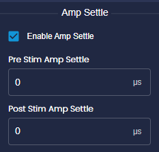
Stimulation can cause large voltage transients that obscure microvolt-level neural signals (e.g., spikes) directly after a pulse. The “amplifier settle” feature is used to reduce the time it takes to return amplifier output to baseline.
This function, when enabled, can be set to activate just before stimulation (usually at zero) and remain for a duration post-stimulation, with 1 ms (1000 μs) being a typical effective duration, but users should experiment with this value to find one optimal for their electrode. Users may also choose to maintain "amp settle" throughout a pulse train or release it after each pulse.
By utilizing the "Enable Amp Settle" option and adjusting the associated parameters, users can effectively manage the impact of stimulation artifacts on amplifier outputs, ensuring accurate and reliable recording and analysis of neural signals.
Charge Recovery
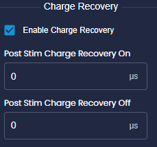
The stim chip's inherent random variations in transistors result in imperfect matching of the positive and negative current sources. This practical limitation prevents the achievement of ideal charge balance. In long-term chronic experiments, residual post-stimulation charge may have negative effects. To mitigate this, the stim chip incorporates a charge recovery feature, which involves forcing an electrode to ground or another fixed voltage.
To enable charge recovery for a specific channel, users can check the "Enable Charge Recovery" box and specify the onset and duration of charge recovery after the stimulation pulse ends. The timing of charge recovery is visually represented by the green bar in the stimulation waveform display.
It's important to note that charge recovery events can introduce recording artifacts due to the application of a large current to the electrode. This current can generate voltage transients in the recording circuitry that may be significantly larger than the desired neural signals. Therefore, careful consideration of the timing and duration of charge recovery events is necessary to minimize their impact on the recorded signals.
Furthermore, it's essential to recognize that charge recovery events may not completely eliminate residual charge on the electrode. Additional techniques such as periodic electrode polarization may be required to maintain optimal electrode performance throughout long-term chronic experiments.
By understanding the implications of charge recovery events and implementing appropriate strategies, researchers can mitigate their potential adverse effects and ensure the integrity of recorded neural signals during stimulation experiments.
Enable Charge Recovery: This option allows the user to enable or disable the post-stimulation charge recovery feature. When enabled, charge recovery is initiated a specified number of microseconds after a stimulation pulse has been sent.
In stimulation protocols, it is common to use charge-balanced pulses to prevent oxidation-reduction reactions at the electrode-tissue interface. However, achieving perfect charge balance is challenging due to inherent variations in transistor characteristics across a chip. To address this issue, recovery circuits are incorporated to dissipate residual charge after stimulation pulses.
One of these circuits is the charge recovery switch, which momentarily connects an electrode to a common stim_GND pin typically tied to ground. Additionally, each channel on the chip includes charge recovery circuits that utilize small programmable currents to pull the electrodes towards a user-defined potential.
To ensure safety and monitor unintended current, the chip also features a global fault current detector that can be inserted into a common return current path, thus detecting any unintended current flow.
By providing the option to enable charge recovery and incorporating various recovery circuits, the system aims to mitigate the effects of residual charge and maintain optimal electrode performance during stimulation experiments.